PRELIMINARY
Samples Q4/2010

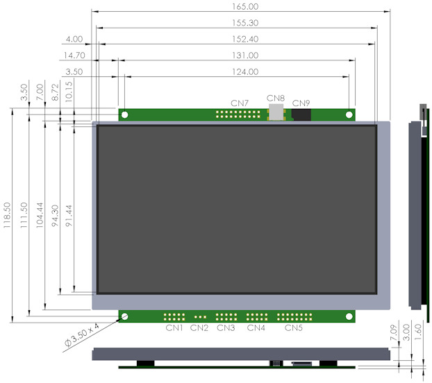
7.0"iSMART TFT Module

800x480 pixels
262,144 Colours (18 bit)
40 Page Display RAM
128M Byte Flash
4G+ Micro SDHC Slot
LED Backlight Control
5V Supply 3.3V Logic
ASCII + UNICODE Fonts

Full RS232 Port
SPI - I2C Interfaces
Sync Serial Controller
USB 2.0 Interface
Analogue Touch Screen
Up to 12 x 12 Key Control
Up to 24 User Digital I/O
2 Analogue Inputs
2 PWM Outputs
Real Time Clock + Date
 
Run Animations
Auto Menu Control
Screen Rotation - 90, 180
Object Oriented Language
Graphic User Interface
Integrated Debugger

Downloads
Specification -


This product has been designed to simplify the implementation of TFT technology into your product. The high level text based object oriented command structure, entity library and 100 page screen memory allow most of the processing to be undertaken by the TFT module leaving the host CPU to concentrate on the core application processes. This allows proven firmware running on small 8 bit microcontrollers to be modified to drive this TFT module with a minimum of work and risk.
 

Module Part Number

Price** RS232 RS485 Touch USB CN8 Battery Holder CANBUS Adaptor Note

TU800X480C-K612A1

      Yes - - - - - -

-K612A1T

€134 Yes - Yes - - - Standard

-K612A1TU*

€135 Yes - Yes Yes - - Can use as Dev Kit

-K612A1TUB

€136 Yes - Yes Yes Yes - Battery not included

-K612A1TUBC

€150

Yes - Yes Yes Yes Yes Battery not included

TU800X480C-K611A1

  Yes Yes - - - - -

-K611A1T

€140 Yes Yes Yes - - - -

-K611A1TU

€141 Yes Yes Yes Yes - - -

-K611A1TUB

€142 Yes Yes Yes Yes Yes - Battery not included

-K611A1TUBC

€156

Yes Yes Yes Yes Yes Yes Battery not included
* Main distributor stock item, other versions supplied to order.  Pre-fitted connector options are available.
** Unit price excludes freight and VAT. Option to pay in GBP £
Optical & Environmental Parameters
Screen Type 800x480 pixels - RGB Stripe - Pixel Pitch 0.19x0.19mm
Display Area 152x91mm - 7.0" diagonal
RGB Colours 262,144 (18 bit)
Display Type Transmissive
Contrast Ratio 250:1
View Angle (typ) 60 degrees
Response Time 25ms @ 25C
Default Viewing Angle 6 o'clock (12 o'clock-Invert the PCB and set 180 degrees orientation in software)
Operating Temperature -20C to +70C
Storage Temperature -30C to +80C
Humidity 20% to 70% RH
Vibration 10-55-10Hz, all amplitude 1mm, 30Min.,  X-Y-Z (Non operating)
Shock 392m/s2 (40G) 9mS X-Y-Z, 3 times each direction (Non operating)
Electrical Parameters
Parameter Sym Min Typ Max Unit Condition Note
Supply Voltage VCC 4.5 5 5.5 VDC VSS=0V Absolute Max 6.0VDC
Logic Supply Output VDD 3.2 3.3 3.4 VDC VCC=5V Max50mA
Logic Input Voltage "H" VIH -0.5 - 3.4 (1) VDC VCC=5V /RES, K0-K24, SCK, /SS, HB, SIN, SCL,SDA
"L" VIL VSS - VSS+0.5 VDC VSS=0V
Logic Output Voltage "H" VOH 3.0 - 3.4 VDC IOH=2mA
VCC=5v
K0-K24, SDA, SCL, SOUT, MB
"L" VOL 0 - 0.7 VDC IOL=-2mA
VCC=5V
"H" Level Logic Input Current IIH - - 1.0 uADC VCC=5.5V /RES, K0-K24, SCK, /SS, SIN, SCL, SDA
"L" Level Logic Input Current IIL - - 1.0 uADC VCC=5.5V
RS232 Input Voltage "H" VIH 2 - 15 VDC VCC=5V RXD, CTS, DSR
"L" VIL -15 - VSS+0.5 VDC VCC=5V
RS232 Output Voltage "H" VOH 4 7 - VDC 3kΩ to GND
VCC=5V
TXD, DTR, RTS
"L" VOL - -7 -4 VDC 3kΩ  to GND
VCC=5V
Power Supply Current 1 ICC1 580 620 650 mADC VCC=5V All dots on
Power Supply Current 2 ICC2 250 270 320 mADC VCC=5V LED Backlight Off
Power Supply Current 3 ICC3 50 60 70 mADC VCC=5V Reset LOW
Note    (1) The voltage applied to logic signals must not exceed the rising VCC at power on as this could affect module initialisation

Connector Pin Assignment
 

CON

Function 1 2 3 4 5 6 7 8 9 10 Note
CN1 Full RS232 Port (6 signals) NC DTR TXD CTS RXD RTS DSR NC GND NC Fits IDC 9 way D type
CN2 5V Power In / Piezo to GND 5V /PZ 0V - - - - - - - Connect piezo negative
CN3 I2C Serial Mode 5V SCL - SDA 0V - - /RES MB HB 3v3 Logic (5v in option)
Asynchronous Serial Mode 5V - SI - 0V - SO /RES MB HB 3v3 Logic (5v in option)
Clock Serial / SPI Mode 5V - RD RCK 0V /RSS TD - /TSS TCK SPI join 4 + 10 and 6+9
CN4 Analogue In, PWN Audio AN1 AN2 0V 5V PW1 PW2 ATX ARX ACK AFS AC97 Audio Pins 7-10
User I/O K16 K17 0V 5V K18 K19 K20 K21 K22 K23 Additional I/O
                         
CON Function 1/2 3/4 5/6 7/8 9/10 11/12 13/14 15/16 17/18 19/20

Note

CN5 USB/ SD Card Extension DA2 CDA CK DA0 0V 0V DM CNX - - SD Card Pins 1-10
USB Pins 11-16
DA3 3V3 0V DA1 CD 5V DP 0V - -
CN7 8x8 Keyboard Matrix and user I/O Ports 5V 3V3 K0 K2 K4 K6 K8 K10 K12 K14 3V3 output max 50mA
0V 0V K1 K3 K5 K7 K9 K11 K13 K15
                         
CN8 USB Connector

Standard Mini B can be omitted on user request. 5V power is then provided from the PC

CN9 SD Card Slot

Micro SD Card holder allows permanent installation for large storage

5V pins are common un-fused input /outputs. 3V3 pins are outputs only with a total 50mA capacity. Do not connect pins '-' or NC


Pin Assignments, Module Dimensions and Function Syntax Copyright 2010 Noritake Co Limited